


- Product Description
-
Order Data
Specifications
Order No.
CPU122,24VDC Power supply,8DI/6DO×24VDC,uni-channel communication
CTS7 112-1AD200X14
CPU122,220VAC power supply,
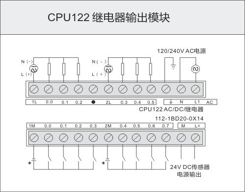
CTS7 112-1BD20-0X14
- Technical Spec
-
Performance Parameters
Physical Features
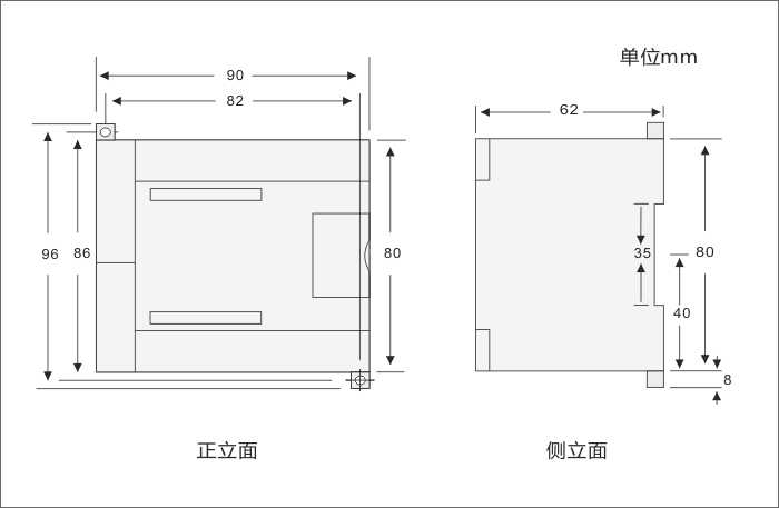
Dimension(W×H×D)
90×80×62mm
Power Dissipation
5W
Memory Features
Program Memory
6KB,4K for common users,2K for encrypted users
Data Memory
2KB
Power-failure retention power
button battery
General Features
Timers in total
1ms
10ms
100ms
128(T0-T127)
4
16
108
Counters in total
128(button battery)
Internal Memory Bits
128(button battery)
Power-failure retention of internal memory
112
Time interrupts
2×1ms Resolution
Edge interrupts
4 rising edges/ falling edges
Boolean execution speed
0.5µs
Float execution speed
16µs
Runtime clock
√
Integrated Communication Function
Communication Port
PORT0:RS485
PPI Baud Rate
9.6, 19.2kbps
Maximum cable length per segment
Isolated repeater applied
Isolated repeater unapplied
When it is 1200 m, 38.4k.
50 m
Maximum number of stations
4 stations per segment,32 stations per network
Maximum number of masters
16
Point to point (PPI Mater Mode)
×
Power Function
Input Voltage
20.4 to 28.8 VDC , with anti- reverse connection protection
+5V power for the extended bus
×
24 VDC Sensor Power supply
×
I/O Features
Number of integrated Digital inputs
8
Input type
Sink/Source
Number of integrated Digital outputs
6
Output type
Solid-MOSFET(Source)
Digital I/O mapping area
128(64 inputs/64 outputs)
Analog I/O mapping area
32(16 inputs/16 outputs)
Maximum number of expandable I/O modules
0
Maximum number of digital I/O
14
Maximum number of analog I/O
0
Pulse catch inputs
8
High-speed counters
Single phase counters
4×50KHz,support HSC0、HSC3、HSC4、HSC5,do not support HSC1and HSC2
Digital Input Features
Number of integrated digital input
8
Input type
Sink/Source
Rated voltage
24V DC
Maximum continuous permissible voltage
30V DC
Logical 1 Signal (minimum)
Logical 0 Signal (Maximum )
14 VDC,2.5mA
5 VDC,1mA
Isolation( field side and logical circuit)
Optical isolation(Galvanic)
Isolation group
√
500V AC,1 minute
refer to the Terminal Identification
Simultaneous Inputs
8
Maximum cable length
Shielded
Unshielded
500 m(standard input)、50m(high-speed counter input)
300 m( standard input)
Digital Output Features
Number of integrated digital output
6
Output type
Solid-MOSFET(Source)
Maximum rated current of each output
Surge Current
0.75A
8A,100 millisecond
Lamp load(Max)
5W
On- state resistance
0.3 ohm , (Max :0.6 ohm )
High-speed pulse output
2×50KHz,Q0.0 and Q0.1, directionless output; Support MC_PTP_R/MC_SPEED_CTRL etc. of CPU, do not support PTO/PWM of programming software
Simultaneous output
6
Two parallel outputs
only when the two outputs are in the same group
Maximum cable length
Shielded
Unshielded
500m(standard output)
150m(standard output)
Performance Parameters
Physical Features
Dimension(W×H×D)
90×80×62mm
Power dissipation
7W
Memory Features
Program memory
6KB,4K for common users,2K for encrypted users
Data memory
2KB
Power-failure retention power
button battery
General Features
Timers in total
1ms
10ms
100ms
128(T0-T127)
4
16
108
Counters in Total
128(button battery)
Internal memory bit
128( button battery)
Power-failure retention of internal memory
112
Time interrupts
2×1ms resolution
Edge interrupts
4 rising edges/ falling edges
Boolean execution speed
0.5µs
Float execution speed
16µs
Runtime clock
√
Integrated Communication Function
Communication port
PORT0:RS485
PPI Baud Rate
9.6, 19.2kbps
Maximum cable length per segment
Isolated repeater applied
Isolated repeater unapplied
When it is 1200 m, 38.4k.
50m
Maximum number of stations
4 stations per segment,32 stations per network
Maximum number of masters
16
Point to point (PPI Mater Mode)
×
Power Function
Input Voltage
85-264VAC(47-63HZ)
+5V power for the extended bus
×
24 VDC Sensor Power supply
240 mA
I/O Features
Number of integrated Digital inputs
8
Input type
Sink/Source
Number of integrated Digital outputs
6
Output type
Relay, dry contact
Digital I/O mapping area
128(64 inputs/64 outputs)
Analog I/O mapping area
32(16 inputs/16 outputs)
Maximum number of expandable I/O modules
0
Maximum number of digital I/O
14
Maximum number of analog I/O
0
Pulse Catch inputs
8
High-speed counters
Single phase counters
4×50KHz,support HSC0、HSC3、HSC4、HSC5, do not support HSC1 and HSC2
Digital Input Features
Number of integrated digital input
8
Input type
Sink/Source
Rated voltage
24V DC
Maximum continuous permissible voltage
30V DC
Logical 1 Signal (minimum)
Logical 0 Signal (Maximum )
14 VDC,2.5mA
5 VDC,1mA
Isolation( field side and logical circuit)
Optical isolation(Galvanic)
Isolation group
√
500V AC,1 minute
refer to the Terminal Identification
Simultaneous Inputs
8
Maximum cable length
Shielded
Unshielded
500 m(standard input)、50m(high-speed counter input)
300 m( standard input)
Digital Output Features
Number of integrated digital output
6
Output type
Relay, dry contact
Maximum rated current of each output
Surge Current
2A
5A,4S@10% duty ratio
Lamp load(Max)
30 WDC/200WAC
On- state resistance
0.2 ohm
Simultaneous output
6
Two parallel outputs
×
Maximum cable length
Shielded
Unshielded
500m(standard output)
150m(standard output)
- Installation
-
Size Diagram:
Wiring Diagram
1.CTS7 112-1AD20-0X14

2.CTS7 112-1BD20-0X14
Definition of Communication PortConnector
PIN
PORT0(RS485)

1
Shell grounded
2
Logical
3
RS-485 Signal B
4
RTS(TTL)
5 Logical
6
+5V,100Ω resistances in series
7
+24V
8
RS-485 Signal A
9
/
Shell
Shell grounded