- Product Description
-
Order data
Specification
Order No.
CTSC-100 CPU124XP,24VDC power supply,12DI×24VDC,8DO×Relay,4AI,2AQ,dual-channel communication
CTS7 114-1BD20-0620
- Technical Spec
-
Performance Parameters
Physical Features
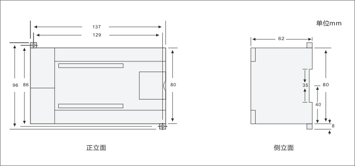
Dimension(W×H×D)
137×80×62mm
Power Dissipation
7W
Physical Features
Program Memory
12KB,8KB for common users,4KBfor encrypted user
Data Memory
8KB
Power-failure retention power
button battery
General Features
Timers in total
1ms
10ms
100ms
128(T0-T127)
4
16
108
Counters in total
128(button battery)
Internal Memory Bits
256(button battery)
ime interrupts
2×1ms resolution
Edge interrupts
4 rising edges/ falling edges
Boolean execution speed
0.5µs
Float execution speed
16µs
Runtime clock
support
Integrated Communication Features
Communication ports
2 (DB9 port);
POTT0:PPI/Freeport, RS485
POTT1:PPI/Freeport, RS485
PPI Baud Rate
PPI Baud Rate
Baud Rate of Freeport
1.2k to 115.2kbps
Maximum cable length per segment
Isolated repeater applied
Isolated repeater unapplied
When it is 1200 m, 38.4k.
50m
Maximum number of stations
32 stations per segment,126stations per network
Maximum number of masters
16
Point to point (PPI Mater Mode)
no
Power Function
Input voltage range
20.4 to 28.8 VDC ,meter protector against fraud protection
Provide for extended bus + 5 V power supply
support,500mA
24 VDC power supply sensor
no
I/O Features
Number of integrated Digital inputs
12
Input type
Sink/Source
Digital output points
8
Output type
relay,dry contacts
Digital I/O mapping area
128 (64Input/64Output)
Analog I/O mapping area
32(16Input/16Output)
Maximum number of expandable I/O modules
3
Maximum number of digital I/O
116
Maximum number of analog I/O
16AI/8AO
Pulse catch inputs
12
High-speed counters
Amount
Single phase counters
Two phase counter
4×50KHz,support HSC0、HSC1、HSC2 and nonsupport HSC3,nonsupport HSC4 and HSC5
1×30KHZ,support 9,HC0
Digital Input Features
Integrated Digital Input
12
Input type
Sink/Source
Rated Voltage
24V DC
Maximum continuous permissible voltage
30V DC
Logical 1 Signal (minimum)
Logical 0 Signal (Maximum )
14 VDC,2.5mA
5 VDC,1mA
Isolation( field side and logical circuit)
Optical isolation(Galvanic)
Isolation group
500V AC,1 minute
Simultaneous Inputs
14
Maximum cable length
Shielded
Unshielded
500 m(standard input)、50m(high-speed counter input)
300 m( standard input)
Digital Output Features
Number of integrated digital output
8
Output type
relay,dry contacts
Maximum rated current of each output
Surge Current
2A
5A,4S@10% duty ratio
Lamp load(Max)
30 WDC/200WAC
On- state resistance
0.2ohm
Simultaneous output
8
Two parallel outputs
only when the two outputs are in the same group
Maximum cable length
Shielded
Unshielded
500m(standard output)
150m(standard output)
Analog Input Features
Input number
4
input mode
single-ended input
Input voltage range
+/-10V
Full range range
-32000~+32000
Input impedance
>100K
Maximum input voltage
30V
Resolution
11bit
isolation
no
Analogue to digital conversion time
50mS
step response
200ms,(0-32000,0-95%)
Noise suppression
Typical values:-40dB◎50HZ
Analog Output Features
Output number
2
Voltage signal range
0~10V
Full range range
0~32000
Resolution
12bit
isolation
no
short-circuit protection
need
Maximum output driver
Voltage output
5000Ωminimum
- Installation
-
Size Diagram:

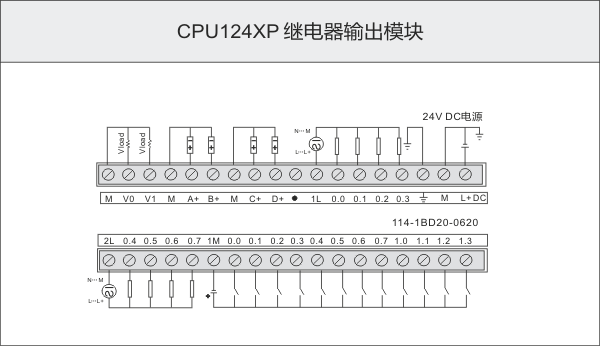
Wiring Diagram:

Definition of Communication Port
Connector
PIN
FPORT(RS485)
PORT0(RS485)

1
Shell grounded
Shell grounded
2
Logical
Logical
3
RS-485 Signal B
RS-485 Signal B
4
RTS(TTL)
RTS(TTL)
5
RTS(TTL)
RTS(TTL)
6
+5V,100Ω resistances in serie
+5V,100Ω resistances in serie
7
+24V
+24V
8
RS-485 Signal A
RS-485 Signal A
9
/
/
Shell
Shell grounded
Shell grounded


