


- Product Description
-
Order Data
Order Data Order No.
Input signal through dual-channel transducer,16bit,sampling rate20Hz(uni-channel)/10Hz(dual-channel),6 VDC,150mA per channel excitation power output CTS7 231-7WB32
- Technical Spec
-
Performance Parameters
Detailed Information:
Major Features:
· Bus and power supply isolation, high reliability, good anti-jamming capability
· 16bit sampling precision, hardware filter technique, more accurate and stable measured
values.
· Reverse protection and surge absorption function of its power supply makes it adaptable to
severe industrial environment.
Use Standard
· use shielded twisted pair to transmit signals and must have one end earthed
· When the system is in a good state, the earthed end must be connected to the ground
wire, otherwise it is not earthed.
· it is suggested to use Trust PLC library function to read data from weigh module
· Calibration needed when replacing modules
When the system is dual-channeled and has one transducer connected, another transducer should be short-circuited to avoid alarm or shift to uni-channel mode.
Specification
CTS7 231-7WB32
Power Consumption
5W
Power Consumption
+5VDC consumed current
<140mA
L+ consumed current
<100mA
L+ Coil voltage range
20.4-28.8VDC
LED indicator
24 VDC Power Supply Good: ON = no fault, OFF = no power ;
SF: ON=module fault, Blink=input signal error, OFF=normal;Input type
Strain gauge,4 or 6wire mode of connection
Input range
0~1mV/V
0~2mV/V
0~3mV/V
0~4mV/V
Input point
2AI
Isolation Features
field side to logic circuit
500VAC
Field side to 24VDC
500VAC
24V to logic circuit
500VAC
Common-mode input range(from input channel to input channel)
0
Common mode rejection
>120dB@120VAC
Input Resolution
temperature coefficient null point
≤±0.1uV/K
Principle of measurement
Sigma-Delta
length of conducting line to transducer
Maximum 500 meters
Noise suppression
85db@50Hz/60Hz
Data word format
Voltage:0 to+32000
Resolution
16 bits
Intrinsic error
0.05%Fs
Repeatability
0.1%Fs
Related Information
Library function of weigh module TrustPLC 231-7WB32.
- Installation
-
Terminal Connection
Weighing module which is a measuring module of high-precision requires reliable measuring low signal level (about 1.5uV). Thus, to make sure it works, it is important to choose appropriate
assembly and cable connection.
While connect weighing transducer, following rules should be obeyed.
· If more than one transducer is going to be connected (if they are weighing transducers,
they must be parallel connected), one junction box must be used. If the distance between
weighing transducer and module or between weighing transducer and junction box is
longer than the length of available cable of weighing transducer, a dedicated extension box
Should be used.
· Shield of cable should always reach as far as to cable gland of junction box or extension box.
· Use stranded wire to connect cable in certain circuit and keep it shielded.
---transducer wire SEN+/SEN-;
---measuring voltage coil SIG+/SIG-;
---supply voltage coil EXC+/EXC-.
·Shielded wire must be joint with shield connector.
Four- Wire connection
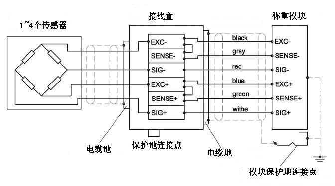
When connect four-wire transducer, please make sure that EXC with SENS, EXC with SENS- are short
circuited. Otherwise, the module may not work normally.
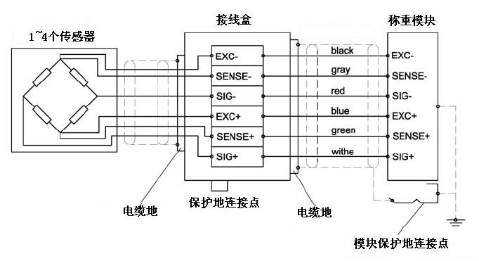
2、Six-wire connection
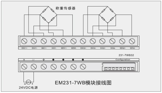
3、Module Connection Diagram
DIP Switch Setting
DIP Switch Configuration
Switch 1、2、3、4、5、6
setting
function
SW1、2
01
Choose 1mV/V transducer
00
Choose 2mV/V transducer
(default)
10
Choose 3mV/V transducer
11
Choose 4mV/V transducer
SW3
0
Choose dual channel working
model (default)
1
Choose uni-channel working
model
SW4
0
Choose filter1(default)
1
Choose filter 2
SW5、6、7、8
00
Spare, reserved
Remark:
Ø Default state:000000
Ø Which filter to be used is determined by software according to need of debug.