


- Product Description
-
Order Data
Order Data Order NO.
CTSC-200 EM231, 4AI×TC, J/K/S/T/R/E/N,+/-80mV CTS7 231-7PD32 CTSC-200 EM231, 8AI×TC, J/K/S/T/R/E/N,+/-80mV CTS7 231-7PF32
- Technical Spec
-
Performance Parameters
Specification
EM231, 4AI×TC
EM231, 8AI×TC
Physical Features
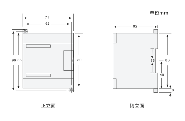
Dimensions(W×H×D)
71.2×80×62mm
71.2×80×62mm Power Loss(dissipation)
1.7W
1.7W Power Consumption From +5V(from I/O bus) 87mA
From L+ 60 mA L+ voltage range,class 2 or DC sensor supply 20.4~28.8V DC LED indicator 24 VDC Power Supply Good: ON = no fault,OFF = no power ;
SF: ON=module fault, Blink=input signal error, OFF=normal;Analog Input Features Input type Floating Thermocouple Input range TC type(select one per module): S, T, R, E, N, K, J
Voltage range: +/-80mVNumber of analog input points 4 points 8 points Isolation Field to Logic
Field to 24V DC
24V DC to logic500V AC
500V AC
500V ACCommon mode input range
(input channel to input channel)120V AC Common mode rejection
>120dB@120V AC
Input resolution Temperature
Voltage
0.1℃/0.1℉
15 bits plus signMeasuring principle
Sigma-Delta Module update time for all channel 425ms 825ms wire length to sensor, maximum 100 m Wire loop resistance 100Ω Suppression of interference 85dB@ 50Hz/60Hz/400Hz Data word format Voltage: -27648 to +27648 Input impedance ≥1MΩ Maximum input voltage 30V DC Input filter attenuation -3dB@ 21kHz Basic error 0.1% FS(Voltage) Repeatability 0.05% FS Cold junction error
±1.5℃ 24V DC supply voltage range 20.4 to 28.8 VDC Configuration
DIP Switches Configuration
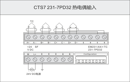
The EM231 TC modules provide a convenient, isolated interface to seven thermocouple types: J, K, E, N, S, T, and R, which also allow the CTS7-200 PLC to connect low level analog signals of 80mV range. You should use the DIP switched to select the thermocouple type, open wire check, temperature scale, cold junction compensation and burnout direction. All thermocouples connect to a module must be of the same type.
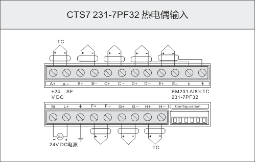
The configuration DIP switches are located on the right bottom of the modules, as shown in the figure 1 and Figure 2, the EM231 4TC module has a 8-pin switches and the EM231 8TC module has a 6-pin switches.
For the DIP switch settings to take effect, you need to power cycle the PLC or the 24V power supply.

Figure 1 EM231 4AI×TC
Figure 2 EM231 8AI×TCSelecting the thermocouple type by setting DIP switch 1 to switch 8 as shown in Table 1 and Table 2 for the EM231 4TC Module, and Selecting the thermocouple type by setting DIP switch 1 to switch 6 as shown in Table 1 and Table 2 for the EM231 8TC Module.
For the EM231 4TC Module, DIP switch 4 is not used, it should be set to the off position. For the EM231 8TC Module, the open wire check is always enable.
Table 1 Selecting the Thermocouple Type
Thermocouple Type SW1 SW2 SW3 J (Default) 0 0 0 K 0 0 1 T 0 1 0 E 0 1 1 R 1 0 0 S 1 0 1 N 1 1 0 +/- 80mV 1 1 1 Table 2 Selecting the others
Feature EM231 4AI×TC EM231 8AI×TC position status position status Burnout Direction SW5 0: Upscale (+3276.7degrees)
1: Downscale (-3276.8degrees)SW4 0: Upscale (+3276.7degrees)
1: Downscale (-3276.8degrees)Open Wire Check SW6 0: enable,
1: disablealways enable Scale Select SW7 0:Celsius (℃),
1:Fahrenheit (℉)SW5 0:Celsius (℃),
1:Fahrenheit (℉)Cold Junction Enable SW8 0: enable
1:disableSW6 0: enable
1:disableSoftware Configuration
The EM231 8AI×TC module has different beginning input address in different slot and its address is not in AIW but in VW, you can calculate the address by the following formula,
x(VWx) = a × 64 + b × 2 (a is the slot no., and b is the point no.)
Table 2 Address for the EM231 8AI×TC
VWxPoint 0Point 1Point 2Point 3Point 4Point 5Point 6Point 7Slot 0VW0VW2VW4VW6VW8VW10VW12VW14Slot 1VW64VW66VW68VW70VW72VW74VW76VW78Slot 2VW128VW130VW132VW134VW136VW138VW140VW142Slot 3VW192VW194VW196VW198VW200VW202VW204VW206Slot 4VW256VW258VW260VW262VW264VW266VW268VW270Slot 5VW320VW322VW324VW326VW328VW330VW332VW334Slot 6VW384VW386VW388VW390VW392VW394VW396VW398Notice: Because the offset address of Td2X text display is also in VW0, so If you need to use Td2X text display in your system, please don’t put the EM231 8AI×TC module in slot 0, or the td2X will not work normally. SIEMENS TD200 text displayer is same as TD2X.(SIEMENS is the trademark of SIEMENS AG.)
- Installation
-
Size Diagram
Wiring Diagram