- Product Description
-
Order Data
Order Data
Order No.
CTSC-200 motion control expand module,24VDC power supply,8DI*24VDC, 8DO*NPN, 2*200KHz input,single phase or A/B,2*200KHz pulse output
CTS7 253-1BH32
- Technical Spec
-
Performance Parameters
Order No.
CTS7 253-1BH32
Physical Features
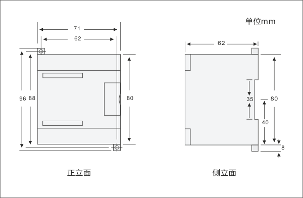
Dimension(W×H×D)
71×62×80mm
Power Dissipation
Power input
20.4 to 28.8VDC,with anti- reverse connection
protection
24 VDC Sensor Power supply
72.7mA
+5V power for the extended bus
217mA
Input Features
Input type
Sink/Source(IEC type 1/Sink)
Number of integrated digital inputs
8
Voltage
24 VDC when 5mA
Maximum continuous permissible voltage
30 VDC
Surge voltage
35 VDC last 0.5 s
Logical 1 Signal (minimum)
When 2.72mA,15.6 VDC(I0.0、I0.1、I0.2、I0.4、I0.5、I0.6)
When2.55mA,12.8VDC(I0.3、I0.7)
Logical 0 Signal (maximum )
When 2.69mA,15.4VDC(I0.0、I0.1、I0.2、I0.4、I0.5、I0.6)
When 2.51mA,12.6 VDC(I0.3、I0.7)
Input lag
< 1.1us (I0.0、I0.1、I0.2、I0.4、I0.5、I0.6)
< 1ms (I0.3、I0.7)
Leakage current allowed(maximum)
1mA
Isolation( field side and logical circuit)
Optical
Isolation group
√
500 VAC,1 minute
Refer to the Terminal Identification
High-speed input rate
High speed counter logic1=16~26 VDC
200KHz(Single-phase,Dual phase)(I0.0、I0.4)
200KHz(A/B phase )(I0.0 and I0.1、I0.4 and I0.5)
Simultaneous output
8
Cable length
(maximum)
isolation
500m standard input,50m high-speed counter input
Not isolation
300m standard input
Output Features
Number of integrated Digital inputs
8
Type
Solid-MOSFET(Sink,NPN)
Power
24 VDC
Output voltage range
5 to 28.8 VDC
Surge current(maximum)
8A last 100ms
Logical 1 Signal (minimum)
20 VDC
Logical 0 Signal (maximum )
0.1 VDC,10KΩ
Rated current(maximum)
0.5A
The current rating of every pin (maximum)
2.0A
Leakage current(maximum)
10μA
Lighting load(maximum)
3.5W
Induction clamping voltage
L+ 48 VDC,1W Power consumption
On resistance
0.3 Ω(0.6Ω maximum)
Isolation
Optical (electrochemical, field side and logical circuit)isolation(Galvanic)
500 VAC,1 minute
Delay(maximum)
Off to on
On to off
0.2μs(Q0.0、Q0.1、Q0.2、Q0.3),50μs(Q0.4、Q0.5、Q0.6、Q0.7)
0.2μs(Q0.0、Q0.1、Q0.2、Q0.3),130μs(Q0.4、Q0.5、Q0.6、Q0.7)
Pulse frequency(maximum)
200KHz(Q0.0、Q0.2)
Outputs at the same time
Output all when 55°C
Two parallel outputs
only when the two outputs are in the
same group
Maximum cable length
Shielded
Unshielded
500m(standard output)
150m(standard output)
Support Instruction
Table Instruction
Function name
Instruction name
Support or not
MC253_INIT_DIR
Configurate motor direction
instruction
Support
MC253_READ_POS
Read position instruction
Support
MC253_PTP_R
Single shaft relative motion
instruction
Support
MC253_SPEED_CTRL
Speed control instruction
Support
MC253_SET_POS_ZERO
Software reset instruction
Support
MC253_SET_POS_PV
Setting target location instruction
Support
MC253_EXT_RESET_EN_EXT
External reset coordinate
enabling instruction
Support
MC253_SET_MAX_ACCELE
Set maximum acceleration
instruction
Support
MC253_PWM
Pulse width modulation instruction
Support
MC253_INIT
Motion control module
initialization instruction
Support,must
be use at initial
MC253_DO_CTRL
Control module output instruction
Support
MC253_READ_DI
Read module input state
instruction
Support
MC253_HSC_INIT
Setting module high speed
counter instruction
Support
MC253_READ_HSC
Read module high speed counter
state instruction
Support
Use standard
1、Support Siemens Micro/win programming but PTO/PWM instruction.Used together CO-TRUST motion control lib :motion_ctrl_module_lib
2、EM253 support CTSC-200 series CPU,it is not compatible with Siemens CPU and CO-TRUST
3、Need to call file motion_ctrl_module_lib when use EM253 DI/DO.For example DI
call MC253_READ_DI,DO call MC253_DO_CTRL
4、EM253 module occupancy analog address 4AI/4AQ,need to clear away the analog address
when want to use
5、Distribute address in the symbol table,attention do not with these address conflict when programming
6、Must be called MC253_INIT instruction when call motion instruction
- Installation
-
Size Diagram

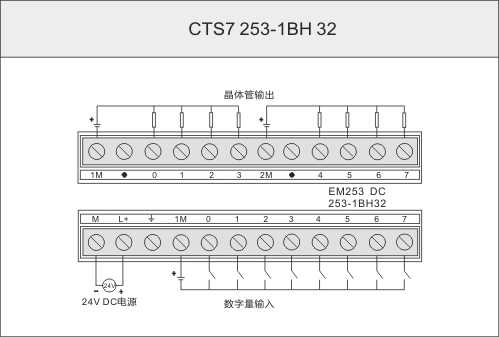
Wiring Diagram


