- Product Description
-
Order Data
Order DataOrder No.CTSC-200 EM231, 4AI×16BIT,10V DC Power, 1ms A/D conversion timeCTS7 231-7HC32
- Technical Spec
-
Performance Parameters
SpecificationEM231, 2 AI×16BITPhysical FeaturesDimensions(W×H×D)71.2×80×62mmPower Loss(dissipation)3.5WPower ConsumptionFrom +5V(from I/O bus)20 mAFrom L+30 mAL+ voltage range,class 2 or DC sensor supply20.4~28.8V DCLED indicator24 VDC Power Supply Good
ON = no fault,
OFF = no 24 VDC powerPower Output FeatureRated voltage output10V DCRated current output10mAOverload protectionYesAnalog Input FeatureNumber of analog input points4 pointsIsolation(field side to logic circuit)Yesinput typeDifferentialInput Range±10V, ±5V,Data RangeBipolar,full-scale range0~32000Unipolar, full-scale range-32000~32000Input ResolutionVoltage(unipolar)0.31mV (0~10V)0.15V (0~5V)Voltage(bipolar)0.61mV (±10V)0.31mV (±5V)Analog to digital conversion time<200μsAnalog input step response<1msCommon mode rejection85dB,DC to 60HzMaximum input voltage30VMaximum input current25mAInverse polarity protectionYesPermissible differential voltageUCM Voltage3VMaximum differential voltage between input ground and power ground75V DCCurrent input0~20mAInput resolution15 bits plus signADC resolution16BITMaximum accuracy± 0.1%Linear accuracy± 0.05 %Configuration
Table 1 shows how to configure the module using the configuration DIP switches,Switches 1, 2, and 3 select the analog input range. All inputs are set to the same analog input range. In this table, ON is closed, and OFF is open. (SW4 to SW5 should be set to the OFF position).Table 1 Configuration Switch Table to select Analog Input Range.SW1SW2SW3Full-Scale InputResolutionOFFOFFON± 10 V312.5uVONOFF± 5 V156.25uVFilter characteristics
Table 2 shows how to configure the module using the configuration DIP switches,Switches 6 select the analog input Filter characteristics.Table 2 Configuration Switch Table to select Analog Input Filter characteristicsSwitchcharacteristicstep response timeSW6OFF:filteringOFF:2 mSON:N0 filteringON:1 mSInput Data Word Format

- Installation
-
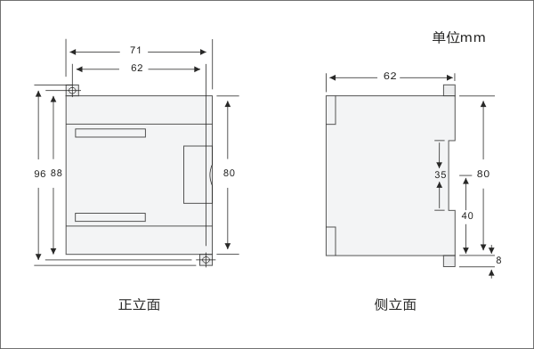
Size Diagram

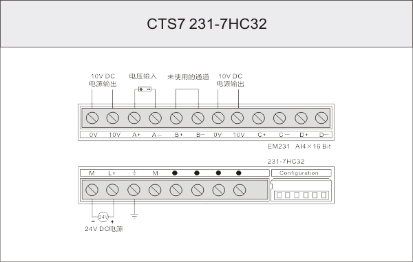
Wiring Diagram


