


- Product Description
-
Order Data
Order DataOrder No.CTSC-200 EM231,8×PID、current input 、0~20mA or 4~20mACTS7 231-7HF32
- Technical Spec
-
Performance Parameters
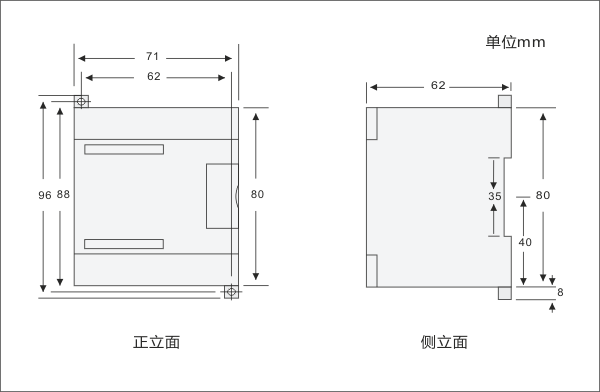
SpecificationEM231, 8×PIDPhysical FeaturesDimensions(W×H×D)71.2×80×62mmPower Loss(dissipation)1.2 WPower ConsumptionFrom +5V(from I/O bus)30mAFrom L+39mAL+ voltage range,class 2 or DC sensor supply20.4~28.8V DCLED indicator24 VDC Power Supply Good: ON = no fault ,OFF = no power ;
SF: ON=module fault, Blink=input signal error, OFF=normal;Analog Input FeaturesInput typecurrent inputInput range0~20mANumber of analog input points8 pointsIsolationField to LogicField to 24V DC
24V DC to logic500V AC
500V AC
500V ACCommon mode input range
(input channel to input channel)120V ACCommon mode rejection>120dB@120V ACInput resolutionTemperatureVoltage0.1℃/0.1℉
15 bits plus signMeasuring principleSigma-DeltaModule update time for all channel825msWire length to sensor, maximum100 mWire loop resistance100ΩSuppression of interference85dB@ 50Hz/60Hz/400HzData word formatVoltage: -27648 to +27648Input impedance≥1MΩMaximum input voltage30V DCInput filter attenuation-3dB@ 21kHzBasic error0.1% FS(Voltage)Repeatability0.05% FSCold junction error±1.5℃24V DC supply voltage range20.4 to 28.8 VDCDiagnostic programLED:EXTF,SFPID FeaturesPID arithmeticPID+FUZZY argument auto-tuningSampling time1 secondMinimum output pulse time10 msPID typeP、PI、PD、PIDPID output typeAnalog or PWMPID output polarityBipolar or unipolarConfiguring PID Address
Calculating the PID address
PID addressFormulaNoteAddress for PID argumentA=(2048+S*256)+16*CS is the installing slot No. of the module (0~6)C is the point no.( 0~7 for 8PID module )Address for PID positive pulseX=(2048+S*256)+12Address for PID negative pulseY=(2048+S*256)+13PID argument output (Module to CPU)
DescriptionAddressSetting ValueActual ValueActual temperatureVM A0~130000~1300℃Status wordVM A+2data readPID analog outputVM A+4-32000~32000-32000~32000PID argument input (CPU to module)
DescriptionAddressSetting ValueActual ValueSetting temperatureVM A+1280~130000~1300℃Control bytesWhen VB A+130 is zeroWhen VB A+130 is 1V( A+130).0PID disable, no outputPID enableV( A+130).1Integral is always active and Kp is not auto tuningIntegral is not active and Kp is auto tuningV( A+130).2Unipolar PID output, 0~32000Bipolar PID output, 32000~32000, with calefaction and cooling functionV( A+130).3UnusedV( A+130).4Integral is activeIntegral is not activeV( A+130).5Differential is activeDifferential is not activeV( A+130).6Filteing for inputNot Filtering for inputPulse output cycle for PIDVW A+1321~2551~255 secondsKpVW A+1340~99990~999.9Ti (Integral time)VW A+1360~36000~3600 secondsTd (differential time)VW A+1380~36000~3600 secondsAddress for positive pulse output
point 0V X.0point 1V X.1point 2V X.2point 3V X.3point 4V X.4point 5V X.5point 6V X.6point 7V X.7Address for negative pulse output
point 0V Y.0point 1V Y.1point 2V Y.2point 3V Y.3point 4V Y.4point 5V Y.5point 6V Y.6point 7V Y.7
- Installation
-
Size Diagram
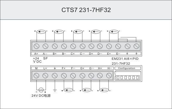
Wiring Diagram
 Configuring DIP switchesThe EM 231 PID modules can only connect to J or K thermocouple type interface, the modules provide a 6-PIN DIP switches, SW1 to SW2 is unused, and SW3 to SW6 is to select thermocouple type,temperature scale, cold junction compensation and burnout direction. the PID modules is always enable open wire check.The configuration DIP switches are located on the right bottom of the module, as shown in the figure below, For the DIP switch settings to take effect, you need to power cycle the PLC and/or the user 24V power supply.
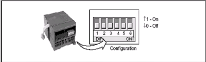
Sw1 Sw2 Sw3 Sw4 Sw5 Sw6 range resolution ON ON OFF OFF OFF OFF 0—20mA 0.1℃/F ON ON ON OFF OFF OFF 4—20mA 0.1℃/F