


- Product Description
-
Order Data
Order Data
Order No.
CTSC-200 EM231, 8AI×16BIT, Cutrrent Input, Isolation CTS7 231-1HF32
- Technical Spec
-
Performance Parameters
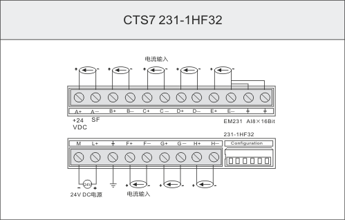
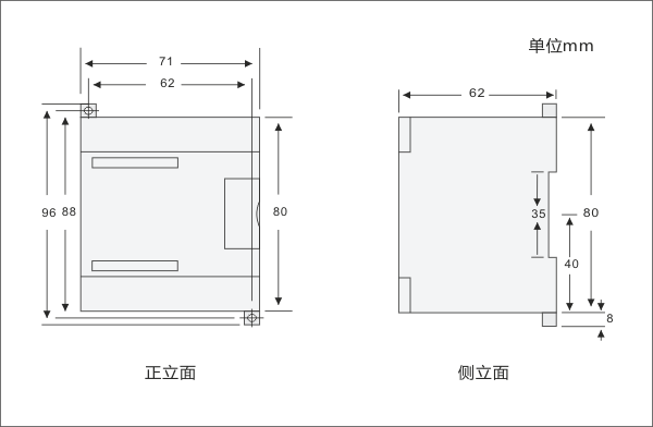
SpecificationEM231, 8 AI×16BITPhysical FeaturesDimensions(W×H×D)71.2×80×62mmPower Loss(dissipation)1WPower ConsumptionFrom +5V(from I/O bus)25 mAFrom L+30 mAL+ voltage range,class 2 or DC sensor supply20.4~28.8V DCLED indicator24 VDC Power Supply Good
ON = no fault,
OFF = no 24 VDC powerAnalog Input FeatureNumber of analog input points8 pointsIsolation(field side to logic circuit)500V AC for 1 minuteinput typeDifferentialInput RangeCurrent ( unipolar )0—20mA 、4—20mAData RangeBipolar, full-scale range0~32000Input Resolutioncurrent (unipolar)0.000625mA (0~20mA)0.0005mA (4~20mA)Analog to digital conversion timeAbout 10msAnalog input step responseAbout 80msCommon mode rejection40dB,DC to 60HzCommon mode voltageSignal voltage plus Common mode voltage must be ≤±12VInput Impedance250ΩInput filter attenuation-3db @ 3.1kHzMaximum input voltage--Maximum input current30mAADC resolution 16BITCalibration and ConfigurationLocation of the calibration and configuration switch

Configuration
Table 1 shows how to configure the EM 231 module using the configuration DIP switches. Switches 1, 2, and 3 select the analog input range. All inputs are set to the same analog input range. In this table, ON is closed, and OFF is open. (SW4 to SW6 should be set to the OFF position)Table 1 EM 231 Configuration Switch Table to select Analog Input RangeUnipolarFull-Scale InputResolutionSW1SW2SW3OFFOFFOFF0 to 20mA0.000625mAOFFON4 to 20mA0.0005mASoftware Configuration
The EM231 8AI module has different beginning input address in different slot and its address is not in AIW but in VW, you can calculate the address by the following formula,x(VWx) = a × 64 + b × 2 (a is the slot no., and b is the point no.)Table 2 Address for the EM231 8AIVWxPoint 0Point 1Point 2Point 3Point 4Point 5Point 6Point 7Slot 0VW0VW2VW4VW6VW8VW10VW12VW14Slot 1VW64VW66VW68VW70VW72VW74VW76VW78Slot 2VW128VW130VW132VW134VW136VW138VW140VW142Slot 3VW192VW194VW196VW198VW200VW202VW204VW206Slot 4VW256VW258VW260VW262VW264VW266VW268VW270Slot 5VW320VW322VW324VW326VW328VW330VW332VW334Slot 6VW384VW386VW388VW390VW392VW394VW396VW398Note: Because the offset address of Td2X text display is also in VW0, so If you need to use Td2X text display in your system, please don’t put the EM231 8AI×TC module in slot 0, or the td2X will not work normally. SIEMENS TD200 text displayer is same as TD2X.(SIEMENS is the trademark of SIEMENS AG.)
- Installation
-
Size Diagram
Wiring Diagram